Machinery Spaces
Home || Diesel Engines ||Boilers||Feed Systems ||Steam Turbines ||Fuel Treatment ||Pumps ||Refrigeration ||

Marine Boiler Combustion Formula - Supply of Air & Fuel Mixing & Soot Blowing

Combustion is the burning of fuel in air in order to release heat energy. For complete and efficient combustion the correct quantities of fuel and air must be supplied to the furnace and ignited. About 14 times as much air as fuel is required for complete combustion.

The air and fuel must be intimately mixed and a small percentage of excess air is usually supplied to ensure that all the fuel is burnt. When the air supply is insufficient the fuel is not completely burnt and black exhaust gases will result.
ships machinery spaces
container ships machinery info
The flow of air through a boiler furnace is known as 'draught'. Marine boilers are arranged for forced draught, i.e. fans which force the air through the furnace. Several arrangements of forced draught are possible. The usual forced draught arrangement is a large fan which supplies air along ducting to the furnace front.

The furnace front has an enclosed box arrangement, known as an 'air register', which can control the air supply.

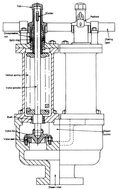
Boiler safety valve
Fig: Ordinary spring-loaded Boiler safety valve

The air ducting normally passes through the boiler exhaust where some air heating can take place. The induced draught arrangement has a fan in the exhaust uptake which draws the air through the furnace. The balanced draught arrangement has matched forced draught and induced draught fans which results in atmospheric pressure in the furnace.


Soot Blowing Procedure

Main Boilers, Auxiliary Boilers & Exhaust Gas Economizers

Soot blowers fitted to Main and Auxiliary boilers, together with Exhaust Gas Economizers, are to be operated prior to arrival in Port and after Full Away On Passage. Under no circumstances are Soot Blowers to be operated during any cargo operations or when a vessel is alongside another vessel or on a berth. During the voyage, soot blowers are to be operated in accordance with manufacturer’s instructions, care being taken during this operation to ensure funnel emissions are not discharged onto cargo areas.


Exhaust Gas Economizers

Water-washing or Exhaust Gas Economizers are to be conducted in port in accordance with the manufacturer’s instructions. Liquid effluent collected from these processes is to be collected and retained in a Soot Wash Tank located onboard. After a period of settlement, the Ph of the liquid is to be chemically neutralised and decanted to the Bilge Tank, ensuring only clear liquid is decanted. This clear effluent decanted to the Bilge Tank is to be processed using the OWS observing standard operating procedures for this equipment, including appropriate entries to the Oil Record book. Details of all above operations are to be recorded in the Machinery Log Book.


The essential requirement for a combustion control system is to correctly proportion the quantities of air and fuel being burnt. This will ensure complete combustion, a minimum of excess air and acceptable exhaust gases. The control system must therefore measure the flow rates of fuel oil and air in order to correctly regulate their proportions.

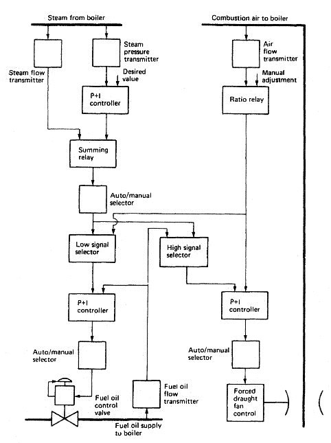
A combustion control system capable of accepting rapid load changes is shown in Figure . Two control elements are used, 'steam flow' and 'steam pressure'. The steam pressure signal is fed to a two-term controller and is compared with the desired value. Any deviation results in a signal to the summing relay.

The steam flow signal is also fed into the summing relay. The summing relay which may add or subtract the input signals provides an output which represents the fuel input requirements of the boiler. This output becomes a variable desired value signal to the two-term controllers in the fuel control and combustion air control loops.

Boiler combustion control

A high or low signal selector is present to ensure that when a load change occurs the combustion air flow is always in excess of the fuel requirements. This prevents poor combustion and black smokey exhaust gases. If the master signal is for an increase in steam flow, then when it is fed to the low signal selector it is blocked since it is the higher input value.

Boiler combustion control
Fig:Boiler combustion control system

When the master signal is input to the high signal selector it passes through as the higher input. This master signal now acts as a variable desired value for the combustion air sub-loop and brings about an increased air flow. When the increased air flow is established its measured value is now the higher input to the low signal selector. The master signal will now pass through to bring about the increased fuel supply to the boiler via the fuel supply sub-loop. The air supply for an increase in load is therefore established before the increase in fuel supply occurs. The required air to fuel ratio is set in the ratio relay in the air flow signal lines.

Emergency fuel shut off valve : The two emergency valves fitted in a boiler fuel system are:
  1. Aquick closing valve on the settling tank which is operated from outside the engine room
  2. safety valves or cocks on each individual burner ­ this valve will operate in the event of high steam pressure, low water level, high water level, flame failure.
Emergency valves on burners have manual shut off for fuel, and automatic shut off in event of boiler fault.

The purpose of the recirculating valve fitted in a boiler fuel system is to enable the fuel oil to be brought up to the desired temperature quickly for combustion.

Note : The boiler fuel oil system can be changed to manual control by means of by-passing the automatic control valve and controlling the fuel oil supply pressure by means of a hand jacking valve on a spring-loaded relief valve governing the discharge pressure from the fuel oil service pumps.


Summarized below marine boiler detail Info pages:

  1. Requirement for various boiler types - water tube boilers and more
  2. The watertube boiler is employed for high-pressure, high-temperature, high-capacity steam applications, e.g. providing steam for main propulsion turbines or cargo pump turbines. Firetube boilers are used for auxiliary purposes to provide smaller quantities of low-pressure steam on diesel engine powered ships.....

  3. Fire tube boilers working principle and operational procedure
  4. The firetube boiler is usually chosen for low-pressure steam production on vessels requiring steam for auxiliary purposes. Operation is simple and feedwater of medium quality may be employed. The name 'tank boiler is sometimes used for firetube boilers because of their large water capacity. The terms 'smoke tube' and 'donkey boiler are also in use....

  5. Exhaust Gas Boilers And Economisers working procedure
  6. The use of exhaust gases from diesel main propulsion engines to generate steam is a means of heat energy recovery and improved plant efficiency.The auxiliary steam installation provided in modern diesel powered tankers usually uses an exhaust gas heat exchanger at the base of the funnel and one or perhaps two watertube boilers .....

  7. The use of boiler mountings
  8. Watertube boilers, because of their smaller water content in relation to their steam raising capacity, require certain additional mountings: Automatic feed water regulator. Fitted in the feed line prior to the main check valve, this device is essential to ensure the correct water level in.the boiler during all load conditions. Boilers with a high evaporation rate will use a multiple-element feed water control system ....

  9. Purity of boiler feedwater
  10. Most 'pure' water will contain some dissolved salts which come out of solution on boiling. These salts then adhere to the heating surfaces as a scale and reduce heat transfer, which can result in local overheating and failure of the tubes. Other salts remain in solution and may produce acids which will attack the metal of the boiler. An excess of alkaline salts in a boiler, together with the effects of operating stresses, will produce a condition known as 'caustic cracking'. This is actual cracking of the metal which may lead to serious failure.....

  11. The steam-to-steam generator working principle and operational procedure
  12. Steam-to-steam generators produce low-pressure saturated steam for domestic and other services. They are used in conjunction with watertube boilers to provide a secondary steam circuit which avoids any possible contamination of the primary-circuit feedwater. The arrangement may be horizontal or vertical with coils within the shell which heat the feedwater.....

  13. How to control combustion in a marine boiler
  14. The essential requirement for a combustion control system is to correctly proportion the quantities of air and fuel being burnt. This will ensure complete combustion, a minimum of excess air and acceptable exhaust gases. The control system must therefore measure the flow rates of fuel oil and air in order to correctly regulate their proportions.....

  15. Safe boiler operation - Preparations & raising steam
  16. All boilers have a furnace or combustion chamber where fuel is burnt to release its energy. Air is supplied to the boiler furnace to enable combustion of the fuel to take place. A large surface area between the combustion chamber and the water enables the energy of combustion, in the form of heat, to be transferred to the water.....

  17. Fuel oil burning process - various design burners
  18. Marine boilers currently burn residual low-grade fuels. This fuel isstored in double-bottom tanks from which it is drawn by a transfer pump up to settling tanks. Here any water in the fuel may settle out and be drained away.

  19. Boiler arrangement - combustion process - supply of air
  20. Combustion is the burning of fuel in air in order to release heat energy. For complete and efficient combustion the correct quantities of fuel and air must be supplied to the furnace and ignited. About 14 times as much air as fuel is required for complete combustion....

  21. Ordinary spring-loaded safety valve and improved high-lift safety valve for a marine boiler
  22. Safety valves are fitted in pairs, usually on a single valve chest. Each valve must be able to release all the steam the boiler can produce without the pressure rising by more than 10% over a set period.....

  23. Correct working level for marine boilers - use of water level gauges
  24. The water level gauge provides a visible indication of the water level in the boiler in the region of the correct working level.

  25. How to maintain water level in a marine boiler ?
  26. A modern high-pressure, high-temperature watertube boiler holds a small quantity of water and produces large quantities of steam. Very careful control of the drum water level is therefore necessary. The reactions of steam and water in the drum are complicated and require a control system based on a number of measured elements......

  27. Safety precautions for working with marine boiler
  28. All boiler controls, regulators, alarms and trips must be tested regularly in accordance with the applicable Planned Maintenance System and maker’s recommendations. Each test is to be recorded with the signature of the Engineer Officer who conducted the test....


Marine machineries - Useful tags

Marine diesel engines ||Steam generating plant ||Air conditioning system ||Compressed air ||Marine batteries ||Cargo refrigeration ||Centrifugal pump ||Various coolers ||Emergency power supply ||Exhaust gas heat exchangers ||Feed system ||Feed extraction pump || Flow measurement || Four stroke engines || Fuel injector || Fuel oil system || Fuel oil treatment ||Gearboxes || Governor || Marine incinerator || Lub oil filters || MAN B&W engine || Marine condensers || Oily water separator || Overspeed protection devices || Piston & piston rings || Crankshaft deflection || Marine pumps || Various refrigerants || Sewage treatment plant || Propellers || Power Plants || Starting air system || Steam turbines || Steering gear || Sulzer engine || Turbine gearing || Turbochargers || Two stroke engines || UMS operations || Drydocking & major repairs || Critical machinery || Deck machineries & cargo gears || Control and instrumentation ||Fire protection ||Engine room safety ||


Machinery Spaces.com is about working principles, construction and operation of all the machinery items in a ship intended primarily for engineers working on board and those who working ashore . For any remarks please Contact us

Copyright © 2010-2016 Machinery Spaces.com All rights reserved.
Terms and conditions of use
Read our privacy policy|| Home page||