Starting air system for Marine diesel engine
Diesel engines are started by supplying compressed air into the cylinders
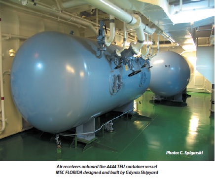
in the appropriate sequence for the required direction. A supply of
compressed air is stored in air reservoirs or 'bottles' ready for immediate
use. Up to 12 starts are possible with the stored quantity of compressed
air. The starting air system usually has interlocks to prevent starting if
everything is not in order.
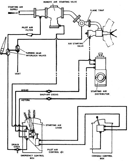
A starting air system is shown in Figure below. Compressed air is supplied by air compressors to the air receivers. The compressed air is then supplied by a large bore pipe to a remote operating non-return or automatic valve and then to the cylinder air start valve. Opening of the cylinder air start valve will admit compressed air into the cylinder.
A starting air system is shown in Figure below. Compressed air is supplied by air compressors to the air receivers. The compressed air is then supplied by a large bore pipe to a remote operating non-return or automatic valve and then to the cylinder air start valve. Opening of the cylinder air start valve will admit compressed air into the cylinder.