Machinery Spaces
Home || Diesel Engines ||Boilers||Feed Systems ||Steam Turbines ||Fuel Treatment ||Pumps ||Refrigeration ||

Oily Water Separator for Marine Machinery Installations

Oil/water separators are used to ensure that ships do not discharge oil when pumping out bilges, oil tanks or any oil-contaminated space. International legislation relating to oil pollution is becoming more and more stringent in the limits set for oil discharge.

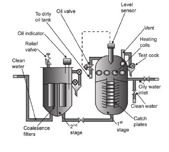
The oily water separator (OWS) is a very important piece of equipment carried on board. It is used to ensure that water is discharged overboard within legal limits. The OWS must be maintained in full working order and operated according to MARPOL regulations.

ships machinery spaces
container ships machinery info
Officers using the equipment must be fully familiar with how it operates. The OWS is frequently inspected at port state inspections. There should also be an OWS operation manual on board and relevant staff should be familiar with the manual and should have practised with the equipment. Please refer to MARPOL Annex 1 and Marlins Course: Oily Water Separators for more information.

Clean water suitable for discharge is defined as that containing less than 15 parts per million of oil. Oil/water separators using the gravity system can only achieve 100 parts per million and must therefore be used in conjunction with some form of filter.

Oily water separator, bilge water separator – A device used to separate oil from oily water mixtures and from the emulsion. Bilge separators are necessary aboard vessels to prevent discharge of oil overboard while pumping out bilges or while cleaning oil tanks. An oilcontent monitor is provided to measure continuously the oil content of the effluent. If the set limit of the oil content is exceeded, the effluent is automatically recirculated to the collecting tank, or the separator is stopped.

Many conventional oily water separators fail to split stable emulsions and remove suspended colloidal particles from the water phase. This often results in equipment malfunction because the separation of oil below 15 ppm is not achieved or because of clogging from excessive solids. 15 ppm bilge separator – Any combination of a separator, a coalescer or other means, and also a single unit designed to produce an effluent with oil content not exceeding 15 parts of oil per million parts of water by volume.

Note: According to Resolution MEPC.107(49), a sampling point should be provided in a vertical section of the water effluent piping as close as practicable to the 15 ppm bilge separator.

Re-circulating facilities should be provided after and adjacent to the overboard outlet of the stopping device to enable the 15 ppm bilge separator system, including the 15 ppm bilge alarm and the automatic stopping device, to be tested with the overboard discharge closed.

One of the main causes of oilywater filtering equipment malfunction is the effect of bilge water containing cleaning agents. Detergent-based cleaning fluids can produce chemically stabilised oil emulsions which cannot be separated on board ship by the gravity alone. The best way to improve the performance of oily bilge water separating equipment is to avoid the use of surfactant-based cleaning materials.

A complete oil/water separator and filter unit for 15 parts per million purity is shown in Figure . The complete unit is first filled with clean water; the oily water mixture is then pumped through the separator inlet pipe into the coarse separating compartment. Here some oil, as a result of its lower density, will separate and rise into the oil collection space. The remaining oil/water mixture now flows down into the fine separating compartment and moves slowly between the catch plates.

Oily water separator
Fig: Oily water separator WÄRTSILÄ SENITEC M1000, capacity 1 m3/hour

Image credit : https://www.wartsila.com
The Wärtsilä Senitec oily water treatment units use optimized emulsion breaking and separation technology that surpasses all existing regulations and guarantees an oil content in the cleaned water of below 5 ppm. In normal operation the actual levels have repeatedly been shown to be as low as 1 ppm, which gives a priceless safety margin to the IMO limit.
In fig Fig: Oily water separator WÄRTSILÄ SENITEC M1000, capacity 1 m3/hour. Principle component as below:
  1. Bilge water inlet
  2. Oil separation stage
  3. Emulsion tank
  4. Chemical dosing pumps
  5. Control panel
  6. Oil and solids effluent
  7. Chemical stage
  8. Dissolved air inlet
  9. Inlet to flotation stage
  10. Overboard
  11. Backwashing water outlet
  12. Fresh water inlet (to filter stage)
  13. Filter stage
  14. Oil monitor
Illustration courtesy of Wärtsilä Corporation Further reading: Wärtsilä Environment Technologies Product Guide


More oil will separate out onto the underside of these plates and travel outwards until it is free to rise into the oil collecting space. The almost oil-free water passes into the central pipe and leaves the separator unit. The purity at this point will be 100 parts per million or less. An automatically controlled valve releases the separated oil to a storage tank. Air is released from the unit by a vent valve. Steam or electric heating coils are provided in the upper and sometimes the lower parts of the separator, depending upon the type of oil to be separated. Where greater purity is required, the almost oil-free water passes to a filter unit.

sketch-oily-water-separator
Simple sketch of oily water separator

The water flows in turn through two filter stages and the oil removed passes to oil collecting spaces. The first-stage filter removes physical impurities present and promotes some fine separation. The second-stage filter uses coalescer inserts to achieve the final de-oiling. Coalescence is the breakdown of surface tension between oil droplets in an oil/water mixture which causes them to join and increase in size. The oil from the collecting spaces is drained away manually, as required, usually about once a week. The filter inserts will require changing, the period of useful life depending upon the operating conditions. Current legislation requires the use of a monitoring unit which continuously records and gives an alarm when levels of discharge in excess of 15 parts per million occur.


Related Info:

Oily water separator regulatory requirement


Other Info pages:
  1. Compressed Air Systems for various shipboard operations
  2. The main aim of a compressor, as the name suggests, is to compress air or any fluid in order to reduce its volume. Some of the main applications of compressors onboard ships are main air compressor, deck air compressor, AC compressor and refrigeration compressor. Failure to start or control air compressor can be inconvenient, costly and can carry risks, which need to be managed.....

  3. Marine air compressors working principles
  4. Control or instrument air supplies have particular requirements with regard to being moisture and oil free and without impurities. A special type of oil-free compressor may be used to supply control air or it may be treated after delivery from an ordinary air compressor. This treatment results in the air being filtered and dried in order to remove virtually all traces of oil, moisture and any atmospheric impurities.....

  5. Coolers at sea- Shell and tube type coolers and plate type coolers
  6. Heat exchangers on board ship are mainly coolers where a hot liquid is cooled by sea water. There are some instances where liquid heating is required, such as heavy fuel oil heaters and sea water heaters for tank cleaning. Although being heat exchangers, the main condenser for a steam ship and the evaporator/distiller are dealt with separately .....

  7. Distillation system- Production of distilled water for ships use - The evaporation process
  8. Distillation is the production of pure water from sea water by evaporation and re-condensing. Distilled water is produced as a result of evaporating sea water either by a boiling or a flash process. This evaporation enables the reduction of the 32000 parts per million of dissolved solids in sea water down to the one or two present in distilled water. The machine used is called an 'evaporator', although the word 'distiller' is also used.....

  9. Oily water separator and filter unit for 15 parts per million purity
  10. Oil/water separators are used to ensure that ships do not discharge oil when pumping out bilges, oil tanks or any oil-contaminated space. International legislation relating to oil pollution is becoming more and more stringent in the limits set for oil discharge.....

  11. Sewage treatment on board- biological and chemical sewage treatment plant
  12. The discharge of untreated sewage in controlled or territorial waters is usually banned by legislation. International legislation is in force to cover any sewage discharges within specified distances from land. As a result, and in order to meet certain standards all new ships have sewage treatment plants installed.....

  13. Where are stabilising fins fitted?- function of it controlling ships motion
  14. Stabilising fins are fitted to ship's sides below the waterline to reduce rolling of the hull by wave action. The fins achieve this by imposing an equal and opposite motion. Retractable fins of aerofoil section use the forward velocity of the ship to create this opposing motion.....

  15. Incinerator for ships
  16. Stricter legislation with regard to pollution of the sea, limits and, in some instances, completely bans the discharge of untreated waste water, sewage, waste oil and sludge. The ultimate situation of no discharge can be achieved by the use of a suitable incinerator. When used in conjunction with a sewage plant and with facilities for burning oil sludges, the incinerator forms a complete waste disposal package.....


Marine machineries - Useful tags

Marine diesel engines ||Steam generating plant ||Air conditioning system ||Compressed air ||Marine batteries ||Cargo refrigeration ||Centrifugal pump ||Various coolers ||Emergency power supply ||Exhaust gas heat exchangers ||Feed system ||Feed extraction pump || Flow measurement || Four stroke engines || Fuel injector || Fuel oil system || Fuel oil treatment ||Gearboxes || Governor || Marine incinerator || Lub oil filters || MAN B&W engine || Marine condensers || Oily water separator || Overspeed protection devices || Piston & piston rings || Crankshaft deflection || Marine pumps || Various refrigerants || Sewage treatment plant || Propellers || Power Plants || Starting air system || Steam turbines || Steering gear || Sulzer engine || Turbine gearing || Turbochargers || Two stroke engines || UMS operations || Drydocking & major repairs || Critical machinery || Deck machineries & cargo gears || Control and instrumentation ||Fire protection ||Engine room safety ||


Machinery Spaces.com is about working principles, construction and operation of all the machinery items in a ship intended primarily for engineers working on board and those who working ashore . For any remarks please Contact us

Copyright © 2010-2016 Machinery Spaces.com All rights reserved.
Terms and conditions of use
Read our privacy policy|| Home page||