Marine Steam Turbines Gearing Arrangement -Epicyclic gearing, Helical gearing, Flexible coupling &Turning gear
Steam turbines operate at speeds up to 6000 rev/min. Medium-speed
diesel engines operate up to about 750rev/min. The best propeller
speed for efficient operation is in the region of 80 to l00 rev/min. The
turbine or engine shaft speed is reduced to that of the propeller by the
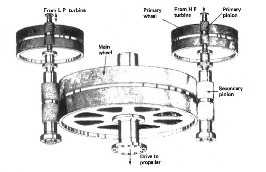
use of a system of gearing. Helical gears have been used for many years
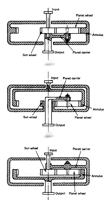
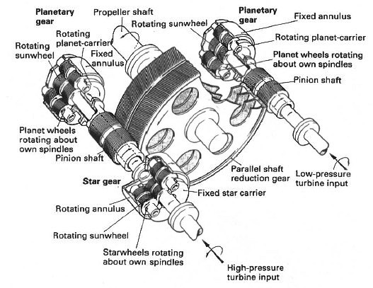
and remain a part of most systems of gearing. Epicyclic gears with their
compact, lightweight, construction are being increasingly used in marine
transmissions.