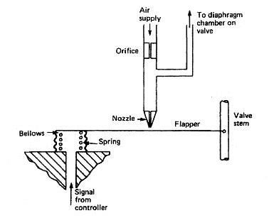
Many pneumatic devices use a nozzle and flapper system to give a
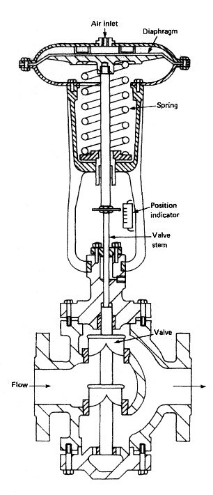
variation in the compressed air signal. A typical pneumatic control valve is shown in Figure . It can be
considered as made up of two partsthe actuator and the valve. In the
arrangement shown a flexible diaphragm forms a pressure tight
chamber in the upper half of the actuator and the controller signal is fed
in.