Machinery Spaces
Home || Diesel Engines ||Boilers||Feed Systems ||Steam Turbines ||Fuel Treatment ||Pumps ||Refrigeration ||

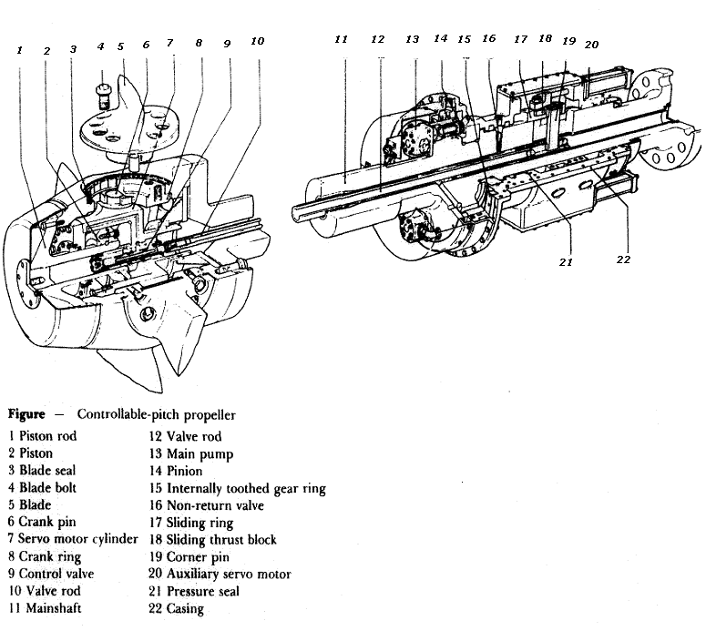
Construction diagram of controllable pitch propeller

A controllable pitch propeller is made up of a boss with separate blades mounted into it. An internal mechanism enables the blades to be moved simultaneously through an arc to change the pitch angle and therefore the pitch. A typical arrangement is shown in Figure below.

When a pitch demand signal is received a spool valve is operated which controls the supply of low-pressure oil to the auxiliary servo motor. The auxiliary servo motor moves the sliding thrust block assembly to position the valve rod which extends into the propeller hub. The valve rod admits high-pressure oil into one side or the other of the main servo motor cylinder. The cylinder movement is transferred by a crank pin and ring to the propeller blades.

ships machinery spaces
container ships machinery info
The propeller blades all rotate together until the feedback signal balances the demand signal and the low-pressure oil to the auxiliary servo motor is cut off. To enable emergency control of propeller pitch in the event of loss of power the spool valves can be operated by hand. The oil pumps are shaft driven. The control mechanism, which is usually hydraulic, passes through the tailshaft and operation is usually from the bridge. Varying the pitch will vary the thrust provided, and since a zero pitch position exists the engine shaft may turn continuously. The blades may rotate to provide astern thrust and therefore the engine does not require to be reversed,


Propeller maintenance

When a ship is in dry dock the opportunity should be taken to thoroughly examine the propeller, and any repairs necessary should be carried out by skilled dockyard staff.

A careful examination should be made around the blade edges for signs of cracks. Even the smallest of cracks should not be ignored as they act to increase stresses locally and can result in the loss of a blade if the propeller receives a sharp blow. Edge cracks should be welded up with suitable electrodes.

Bent blades, particularly at the tips, should receive attention as soon as possible. Except for slight deformation the application of heat will be required. This must be followed by more general heating in order to stress relieve the area around the repair.

Surface roughness caused by slight pitting can be lightly ground out and the area polished. More serious damage should be made good by welding and subsequent heat treatment. A temporary repair for deep pits or holes could be done with a suitable resin filler.


Controllable pitch propeller
Fig: Controllable pitch propeller

Related information

  1. Oil lubricated sterntube bearing, sterntube seals & shafting arrangement
  2. The sterntube bearing serves two important purposes. It supports the tailshaft and a considerable proportion of the propeller weight. It also acts as a gland to prevent the entry of sea water to the machinery space.....

  3. Function of solid fixed pitch propeller & Propeller mounting
  4. The propeller consists of a boss with several blades of helicoidal form attached to it. When rotated it 'screws' or thrusts its way through the water by giving momentum to the column of water passing through it. The thrust is transmitted along the shafting to the thrust block and finally to the ship's structure....

  5. Controllable pitch propeller
  6. A controllable pitch propeller is made up of a boss with separate blades mounted into it. An internal mechanism enables the blades to be moved simultaneously through an arc to change the pitch angle and therefore the pitch....

  7. Ships propeller shaft -Thrust block & Shaft bearings
  8. The transmission system on a ship transmits power from the engine to the propeller. It is made up of shafts, bearings, and Finally the propeller itself. The thrust from the propeller is transferred to the ship through the transmission system....


Marine machineries - Useful tags

Marine diesel engines ||Steam generating plant ||Air conditioning system ||Compressed air ||Marine batteries ||Cargo refrigeration ||Centrifugal pump ||Various coolers ||Emergency power supply ||Exhaust gas heat exchangers ||Feed system ||Feed extraction pump || Flow measurement || Four stroke engines || Fuel injector || Fuel oil system || Fuel oil treatment ||Gearboxes || Governor || Marine incinerator || Lub oil filters || MAN B&W engine || Marine condensers || Oily water separator || Overspeed protection devices || Piston & piston rings || Crankshaft deflection || Marine pumps || Various refrigerants || Sewage treatment plant || Propellers || Power Plants || Starting air system || Steam turbines || Steering gear || Sulzer engine || Turbine gearing || Turbochargers || Two stroke engines || UMS operations || Drydocking & major repairs || Critical machinery || Deck machineries & cargo gears || Control and instrumentation ||Fire protection ||Engine room safety ||


Machinery Spaces.com is about working principles, construction and operation of all the machinery items in a ship intended primarily for engineers working on board and those who working ashore . For any remarks please Contact us

Copyright © 2010-2016 Machinery Spaces.com All rights reserved.
Terms and conditions of use
Read our privacy policy|| Home page||