Machinery Spaces
Home || Diesel Engines ||Boilers||Feed Systems ||Steam Turbines ||Fuel Treatment ||Pumps ||Refrigeration ||

CO2 Fire Extinguishing Installations for Ships Machinery Spaces

A carbon dioxide flooding system is used to displace the oxygen in the protected space and thus extinguish the fire. The carbon dioxide is stored as a liquid under pressure in cylinders.

The volume of space to be protected determines the number of cylinders required. A common battery of cylinders may be used to protect both cargo holds and machinery space.
ships machinery spaces
container ships machinery info
The cargo space system is normally arranged for smoke detection, alarm and carbon dioxide flooding (Figure below). Small air sampling pipes from the individual cargo holds are led into a cabinet on the bridge. Air is drawn from each hold by a small fan and each pipe is identified for its particular hold. If smoke is drawn into the cabinet from one of the holds it will set off an alarm.

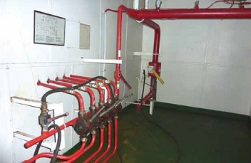
typical CO2 piping
Typical CO2 piping

The smoke is also passed into the wheelhouse where it can be detected by personnel on watch.

The location of the fire can be identified in the cabinet and the hold distribution valve below the cabinet is operated. This valve shuts off the sampling pipe from the cabinet and opens it to the carbon dioxide main leading from the cylinder battery. A chart will indicate the number of cylinders of gas to be released into the space and this is done by a hand operated lever.

CO2 flooding system
Fig: CO2 flooding system

The machinery space system is designed to quickly discharge the complete battery of cylinders. Before the gas is released the space must be clear of personnel and sealed against entry or exhausting of air. The discharge valve is located in a locked cabinet, with the key in a glass case nearby. Opening the cabinet sounds an alarm to warn personnel of the imminent discharge of the gas. The discharge valve is opened and an operating lever pulled.

The operating lever opens two gas bottles which pressurise a gang release cylinder that, in turn, moves an operating cable to open all the bottles in the battery. The carbon dioxide gas then quickly floods the machinery space, filling it to 30% of its volume in two minutes or Jess.

The air sampling system can be checked when the holds are empty by using a smoking rag beneath a sampling point. Flow indicators, usually small propellers, are fitted at the outlet points of the smoke detecting pipes as a visual check and an assurance that the pipes are clear. To check for leakage the gas cylinders can be weighed or have their liquid levels measured by a special unit.


CO2 installations - System requirement

Fire extinguishing installations employing CO 2 stored under pressure at ambient temperature are extensively used to protect ships' cargo compartments, boiler rooms and machinery spaces. When released the CO 2 is distributed throughout the compartment, so diminishing the relative oxygen content and rendering the atmosphere inert.

The quantity of CO 2 required is calculated from the gross volume of the largest cargo space or machinery compartment, whichever is the greater of the two. Additional CO 2 may be required for machinery spaces containing large air receivers. This is because air released from the cylinders through fusible plugs or over pressure release, would increase oxygen content in the space.

CO2 fire extinguishing installations
Fig : CO2 fire extinguishing installations

The high pressure carbon dioxide (CO 2 ) system shown (Figure above) is supplied from storage bottles of CO 2 which are opened by a servo-piston operated gang release. A safety feature to protect against accidental release is provided by the master valve on the pipe to the engine room distribution nozzles. The CO 2 system is used if a fire is severe enough to force evacuation of the engine room or to prevent entry. An alarm is sounded by an alarm button as the CO 2 cabinet is opened and in some ships there is also a stop for the engine room fans incorporated (Figure below).

CO2 cabinet alarm
Fig : CO2 cabinet alarm

Before releasing the CO 2 , personnel must be accounted for and the engine room must be in a shut down condition with all openings and vent flaps closed. It is a requirement that 85% of the required quantity of gas is released into the space within two minutes of actuating the system release. In the installation shown, the actuating handle opens pilot cylinders of CO 2 and the gas from these pushes the piston in the servo-cylinder down, to operate the gang release for the other bottles. To avoid sticking, all the handles must be in good alignment. The bottle valves may be of the quick-release type (Figure below) where the combined seal and bursting disc is pierced by a cutter. The latter is hollow for passage of liquid CO 2 to the discharge pipe.

CO2 cutter type quick release
Fig : CO2 cutter type quick release


An alternative type of quick release valve is held in place by a hinged linkage arrangement until released. Bottle pressure is normally about 5 2 bar (750lb/in ) but this varies with 2 temperature. Bottles should not be stored where the temperature is likely to exceed 55 degree C. The seal/bursting discs are designed to rupture spontaneously at pressures of 177 bar produced by a temperature of about 63°C. The master valve prevents CO 2 released in this way from reaching the engine room. Gas is released by the relief arrangement on the manifold, into the CO 2 space where, in the event that the release was caused by a fire in the compartment, the fire would be extinguished.

Rapid injection of CO 2 is necessary to combat an engine room fire which has attained such magnitude that the space has to be evacuated. Hence the rule that 85% of the gas must be released within two minutes. The quantity of gas carried (a) must be sufficient to give a free gas volume equal to 40% of the volume of the space except where the horizontal casing area is less than 40% of the general area of the space, or (b) must give a free gas volume equal to 35% of the entire space, whichever is greater. The free air volume of air receivers may have to be taken into consideration. The closing of all engine room openings and vent flaps will prevent entry of air to the space. All fans and pumps for fuel, can be shut down remotely as can valves on fuel pipes from fuel service and storage tanks.

CO 2 bottles are of solid drawn steel, hydraulically tested to 228 bar. The contents are checked by weighing or by means of a radioactive level indicator. Recharging is necessary if there is a 10% weight loss. Pipework is of solid drawn mild steel, galvanized for protection against corrosion. The syphon tube in the bottle ensures that liquid is discharged from the bottles. Without the syphon tube the CO2 would evaporate from the surface giving a very slow discharge rate and, taking latent heat, would probably cause the remaining CO2 in the bottle to freeze.

CO2 piping

Relatively small bore hot galvanised mild steel piping designed to withstand the surge loads that occur with the release of CO2. Main CO2 lines are designed to withstand the same pressure as that of CO2 bottles, while distribution lines off the main valve are designed for a lower pressure. Typically, the main line is pressure tested to 200 bar, the design pressure being at least 160 bar.


Fixed installations

A variety of different fixed fire fighting installations exist, some of which are specifically designed for certain types of ship. A selection of the more general installations will now be outlined.
  1. Fire main system for cargo ships

  2. An outbreak of fire requires a source of ignition, the presence of combustible material and ample oxygen. Of the three factors, oxygen is provided in large quantities in machinery spaces, accommodation, dry cargo holds and tanker pumprooms by ventilation fans. Air supply trunkings are not only a source for a supply of oxygen to feed the fire but also have potential for carrying smoke from one area to another....

  3. Automatic water spray & water mist system for machinery protected area

  4. The automatic spray or sprinker system provides a network of sprinkler heads throughout the protected spaces. This system may be used in accommodation areas, and in machinery spaces with certain variations in the equipment used and the method of operation. ....

  5. Automatic foam induction system for machinery space fire

  6. Foam spreading systems are designed to suit the particular ship's requirements with regard to quantity of foam, areas to be protected, etc. Mechanical foam is the usual substance used, being produced by mixing foam making liquid with large quantities of water. Violent agitation of the mixture in air creates air bubbles in the foam. ...

  7. CO2 fire extinguishing installations for machinery spaces

  8. Fire extinguishing installations employing CO 2 stored under pressure at ambient temperature are extensively used to protect ships' cargo compartments, boiler rooms and machinery spaces. When released the CO 2 is distributed throughout the compartment, so diminishing the relative oxygen content and rendering the atmosphere inert....

  9. Inert gas systems, inert gas generator

  10. Inert gases are those which do not support combustion and are largely nitrogen and carbon dioxide. Large quantities suitable for fire extinguishing can be obtained by burning fuel in carefully measured amounts or by cleaning the exhaust gases from a boiler. ....

  11. Fire fighting Halon system

  12. A Halon storage system would be very similar to one using carbon dioxide except that fewer cylinders would be required. The liquefied Halon is usually pressurised in the cylinders with nitrogen in order to increase the speed of discharge. ....


Marine machineries - Useful tags

Marine diesel engines ||Steam generating plant ||Air conditioning system ||Compressed air ||Marine batteries ||Cargo refrigeration ||Centrifugal pump ||Various coolers ||Emergency power supply ||Exhaust gas heat exchangers ||Feed system ||Feed extraction pump || Flow measurement || Four stroke engines || Fuel injector || Fuel oil system || Fuel oil treatment ||Gearboxes || Governor || Marine incinerator || Lub oil filters || MAN B&W engine || Marine condensers || Oily water separator || Overspeed protection devices || Piston & piston rings || Crankshaft deflection || Marine pumps || Various refrigerants || Sewage treatment plant || Propellers || Power Plants || Starting air system || Steam turbines || Steering gear || Sulzer engine || Turbine gearing || Turbochargers || Two stroke engines || UMS operations || Drydocking & major repairs || Critical machinery || Deck machineries & cargo gears || Control and instrumentation ||Fire protection ||Engine room safety ||


Machinery Spaces.com is about working principles, construction and operation of all the machinery items in a ship intended primarily for engineers working on board and those who working ashore . For any remarks please Contact us

Copyright © 2010-2016 Machinery Spaces.com All rights reserved.
Terms and conditions of use
Read our privacy policy|| Home page||