Machinery Spaces
Home || Diesel Engines ||Boilers||Feed Systems ||Steam Turbines ||Fuel Treatment ||Pumps ||Refrigeration ||

Electric Drives for Deck Mooring Equipment

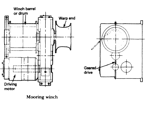
Winches with various arrangements of barrels are the usual mooring equipment used on board ships. A mooring winch is shown in Figure below where the various parts can be identified. The winch barrel or drum is used for hauling in or letting out the wires or ropes which will fasten the ship to the shore. The warp end is used when moving the ship using ropes or wires fastened to bollards ashore and wrapped around the warp end of the winch.

ships machinery spaces
container ships machinery info
The construction of a mooring winch will now be examined, again with respect to Figure below. The motor drive is passed through a spur

gear transmission, a clutch and thus to the drum and warp end. A substantial frame supports the assembly and a band brake is used to hold the drum when required. The control arrangements for the drive motor permit forward or reverse rotation together with a selection of speeds during operation.

Modern mooring winches are arranged as automatic self-tensioning units. The flow of the tides or changes in draught due to cargo operations may result in tensioning or slackening of mooring wires. To avoid constant attention to the mooring wires the automatic selftensioning arrangement provides for paying out (releasing) or recovering wire when a pre-set tension is not present.

Deck mooring winch
Figure : Deck mooring winch


Most deck machinery is idle during much of its life while the ship is at sea. In port, cargo equipment will be in use for one or more days but the machinery for anchoring and mooring is used for a very limited time. Deck machinery with a restricted and intermittent duty may be designed with drives with a rating limited from 30 minutes to one hour. Despite long periods of idleness, often in severe weather conditions, machinery must operate immediately, when required. Cooling vents, open when machinery is working, must be closed for the sea passage.

Electric drive for running deck machineries on cargo ship

Electric motors on vulnerable deck areas may be protected against ingress of water by being totally enclosed in a watertight casing. Vents are provided on some winches, which must be opened when the motor is operating in port.

The direct current (d.c.) motor, although it is relatively costly and requires regular brush gear maintenance, is still used for deck machinery because it has a full speed range with good torque at any speed.

The control of d.c. motors by contactor-switched armature resistances, common in the days when ships' electrical supplies were d.c., has long been replaced by a variety of Ward-Leonard type systems which give a better, more positive regulation particularly for controlled lowering of loads. The Ward-Leonard generator is normally driven by an a.c. motor.

An important feature of the d.c. drive is its efficiency, particularly in comparison with a.c. drives, when operating at speeds in the lower portion of the working range. The d.c. motor is the only electric drive at present in production which can be designed to operate in a stalled condition continuously against its full rate torque and this feature is used for automatic mooring winches of the 'live motor' type.

The majority of d.c. winch motors develop full output at speeds of the order of 500 rev/min and where necessary are arranged to run up to two to four times this speed for light line duties. Windlass motors on the other hand do not normally operate with a run up in excess of 2 : 1 and usually have a full load working speed of the order of 1000 rev/min.

Direct current motors may also be controlled by static thyristor converters which convert the a.c. supply into a variable d.c. voltage of the required magnitude for any required armature speed. These converters must be of a type capable of controlled rectification and inversion with bi-directional current flow if full control is to be obtained

Alternating current induction motors, of either the wound rotor or of the winch. means of pole changing connections and in the case of the wound rotor induction motor, also by changing the value of the outside resistance connected in the rotor circuit. The pole change method involves the switching of high currents at medium voltage in several lines simultaneously, requiring the use of multi-pole contactors. The pole change speed control method offers a choice of perhaps three discrete speeds such as 0.65, 0.325 and 0.1025 m/s corresponding to 4, 8 and 24 pole operation.

The wound rotor motor is flexible when hoisting a load, because the starting resistances can be reintroduced into the rotor circuit and the load will cause the motor to slip. The slip gives a range between the speeds dictated by the pole arrangement. As with resistance controlled d.c. motors, difficulty is experienced when providing speed control of an overhauling load, i.e. lowering a suspended load. The disadvantages must be balanced against lower cost, particularly of the cage type induction motor, in comparison with the more flexible d.c. motor.

Another form of induction motor control system is based on the relationship between output torque and applied voltage, the torque being proportional to the voltage squared. The controller takes can only be achieved by this means if a closed loop servo control system is used in conjunction with a very fast acting regulator which automatically adjusts the output torque to suit the load demand at the set speed. Control of an overhauling load is made possible by using injection braking techniques. A combined system employing both these control principles can provide full control requirements for all deck machinery.

The a.c. drives described operate at the supply frequency and consequently rapid heating of the motor will occur if the drive is stalled when energized. The majority of a.c. motors on deck machinery run at a maximum speed corresponding to the 4 pole synchronous speed of 1800 rev/min on a 60 Hz supply. These speeds are similar to the maximum speeds used with d.c. drives and the bearings and shaft details tend to be much the same. The motor bearings are normally grease lubricated. However, where the motor is flange mounted on an oil bath gearcase,


Marine machineries - Useful tags

Marine diesel engines ||Steam generating plant ||Air conditioning system ||Compressed air ||Marine batteries ||Cargo refrigeration ||Centrifugal pump ||Various coolers ||Emergency power supply ||Exhaust gas heat exchangers ||Feed system ||Feed extraction pump || Flow measurement || Four stroke engines || Fuel injector || Fuel oil system || Fuel oil treatment ||Gearboxes || Governor || Marine incinerator || Lub oil filters || MAN B&W engine || Marine condensers || Oily water separator || Overspeed protection devices || Piston & piston rings || Crankshaft deflection || Marine pumps || Various refrigerants || Sewage treatment plant || Propellers || Power Plants || Starting air system || Steam turbines || Steering gear || Sulzer engine || Turbine gearing || Turbochargers || Two stroke engines || UMS operations || Drydocking & major repairs || Critical machinery || Deck machineries & cargo gears || Control and instrumentation ||Fire protection ||Engine room safety ||


Machinery Spaces.com is about working principles, construction and operation of all the machinery items in a ship intended primarily for engineers working on board and those who working ashore . For any remarks please Contact us

Copyright © 2010-2016 Machinery Spaces.com All rights reserved.
Terms and conditions of use
Read our privacy policy|| Home page||